Introduction
Hey everyone in this tutorial. I’ll show you how you can make this custom PCB badge. Which has few leds and some electronics for some fun!
So without any further ado lets get started.
Step 1: Circuit
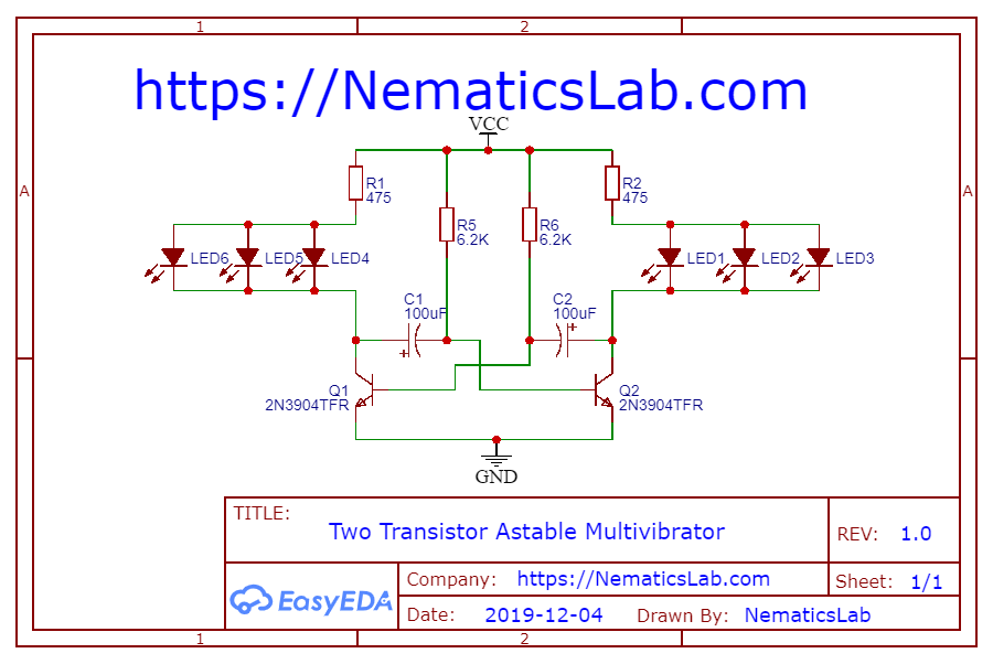
Lets start with the circuit I used for the flashing the LEDs. And Here is the schematic you can download it from my website link is in the video description.
This circuit is called Two transistor a stable multivibrator or you can call it a oscillator. I wont go into much details right now but If you guys want a tutorial on Multivibrators. Let me know in the comment section below.
Anyways this circuits basically uses two transistors to toggle LEDs alternatively using some Capacitors & Resistors. You can adjust the Time delay between the toggles using this formula.
T=2*0.68*RC
I choose a relatively small time of about 0.85 Seconds. And used a 100uF capacitor and I got a resistance value of about 6.25Kohm. Which then I rounded of to 6.2Kohm because that was the nearest value available.
Step 2: Making PCB

After which I tested the circuit on bread board and it seems to work just fine. So I converted the schematic into PCB layout using the Easyeda online PCB designing software. And here starts the fun part.
You can make any design you want of your PCB I wanted it to look like a cool Badge. Which I can wear on my shirt to Promote My YouTube channel so I went with this Funky looking Hexagonal shape.
Also, I used all the SMD components to keep the weight of PCB as low as possible. Once I was done with the design, I exported the Gerber file and Uploaded it to
https://JLCPCB.com who are also the sponsor of this project. This time around I wanted to try out their SMD Assembly service. So I clicked on Assemble PCB button on their website and the process was pretty Straight forward. And I only had to upload two extra files for getting my PCB assembled from JLC PCB.com.
Again, I won’t go into much details As I plan to make a dedicated video tutorial. About that you can check out JLCPCB.com link is in the video description.
Step 3 PCB Badge Testing
Once I got my PCBs, I really wanted to make sure if quality of silkscreen was good. So scanned the QR code and it worked like charm. Then I simply soldered a 500mA Li-po Battery and tested if the circuit worked and it did without any problem.
After which I removed the battery and proceeded towards soldering a Safety pin which I stole from my mom 😛
Once that was done. Later I realized I forgot to add a power switch. So I added a simple tactile switch, directly on the pads on PCB and soldered battery via it. After using some hot glue to secure the tactile switch in its position this project was complete!
Check out this awesome project as well –https://nematicslab.com/home-automation-using-nodemcu-esp8266-blynk/


