Introduction,
Hi and welcome back to a new tutorial, Today I’ll show you how to use a breadboard. And this is one of the most basic things you will need to learn. If you want to get yourself started with electronics. And best part is that I can guarantee you will never stop using a breadboard for rest of your life.
So, without any further ado let’s get started!
Why breadboard is used?

If you are just getting started with electronics soldering is probably something you are not familiar with. Hence, we need some alternative which is solderless and beginners friendly.
What does Breadboard look like? and some tips,
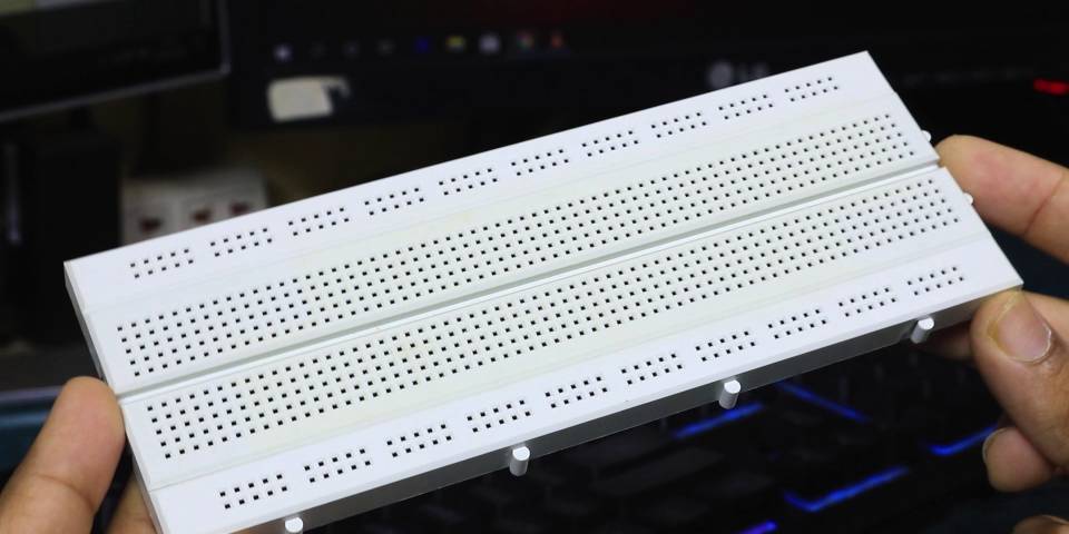
This is how a generally a full-size breadboard looks like. They come is different sizes and colors it doesn’t really matter what size you get. But I’ll highly recommend getting a full size one.
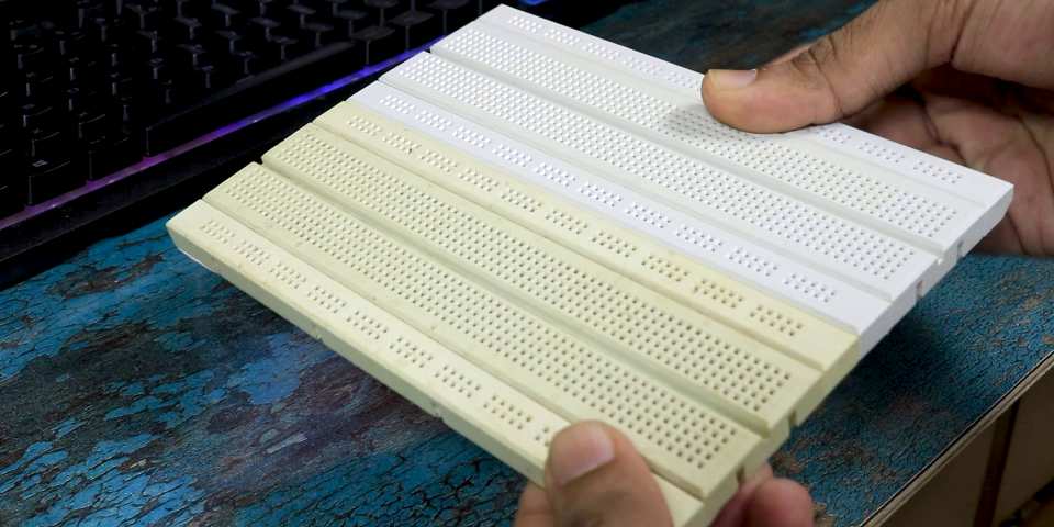
If you have more than one breadboard you can easily combine them like thing using these tabs. To form a even larger breadboard.
Understanding the internal Connections,
Now coming to the point how do you use one? Well before using one you need to understand the how is a breadboard internally connected.
Pretty much All full-size breadboard has 2 parts, Power line & the Prototyping space.
Power Lines


This is your power line and as you can see there are two of them for your convenience. These powerlines are connected vertically(Along its larger side) in set of 5 in a full size breadboard. Which means this power line is connected vertically from here to here. Then there is a break point after 5th slot here and again it is connected in similar fashion.
They are connected only vertically not horizontally. So Let’s say if I connect my 5V over here and GND over here then. There will be 5V & GND in these rows.
If you want to get 5V & GND to below as well then you need to add a jumper cable.
Prototyping space
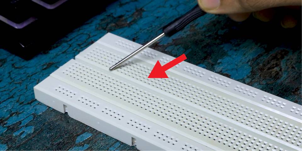
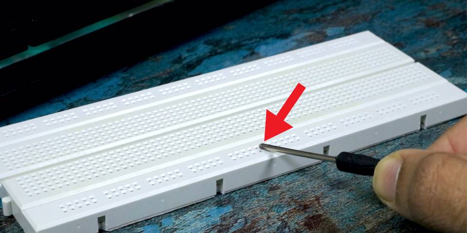
Now lets talk about prototyping space. Unlike Power lines these points are connected horizontally. In two sets from over here to here then there this breakpoint along entire breadboard. And again, it continues from here to here.

To make this thing clear I’ll remove the back tape of breadboard. And you can clearly see what I was talking about.
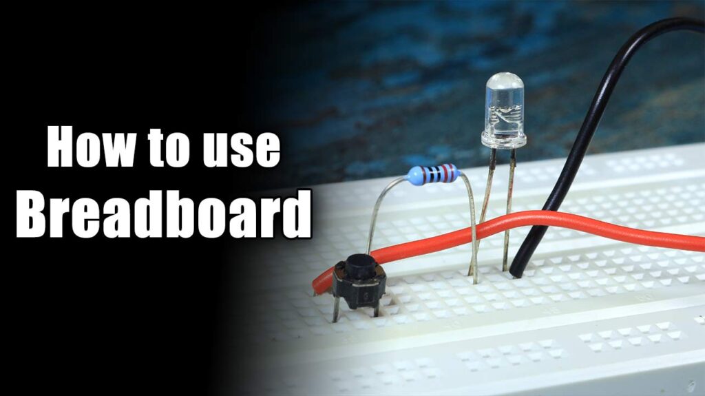
Lets build a circuit!


So lets say if you want to connect your LED to Breadboard. So, you will connect it like this. Such that this entire line will be Anode of LED and this entire Line will be Cathode of your LED. Now if you wish to add a resistor you can simply add it like this. Lets also add a a tactile switch and after adding some power if I press this switch LED will glow.


Finally, here is how you connect an IC & LED to the Breadboard. You should always connect and IC separated by middle line. Which means like this and not like this!
If you enjoyed this Post make sure to check out this one! – https://nematicslab.com/amazon-alexa-on-raspberry-pi/