
Introduction,
Hi and welcome back to a new tutorial. In this tutorial we are going to make this simple 3 Transistor contact less Mains voltage detector circuit. And understand how it works. Which can be really useful if you are working with mains voltage. And best part is that its contact less so without any further ado lets get started!
Everything we need
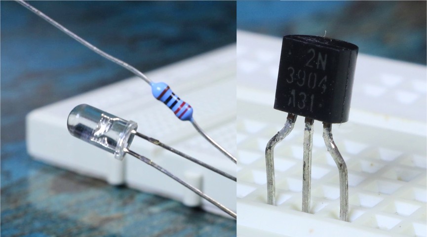
To make this project all you need is 3 NPN transistors. I used 3904 because I had them lying around but you can use pretty much any general purpose NPN transistor. Like 2N2222 or BC547. Along with that we also need one LED & 220 Ohm Current limiting resistor for LED.
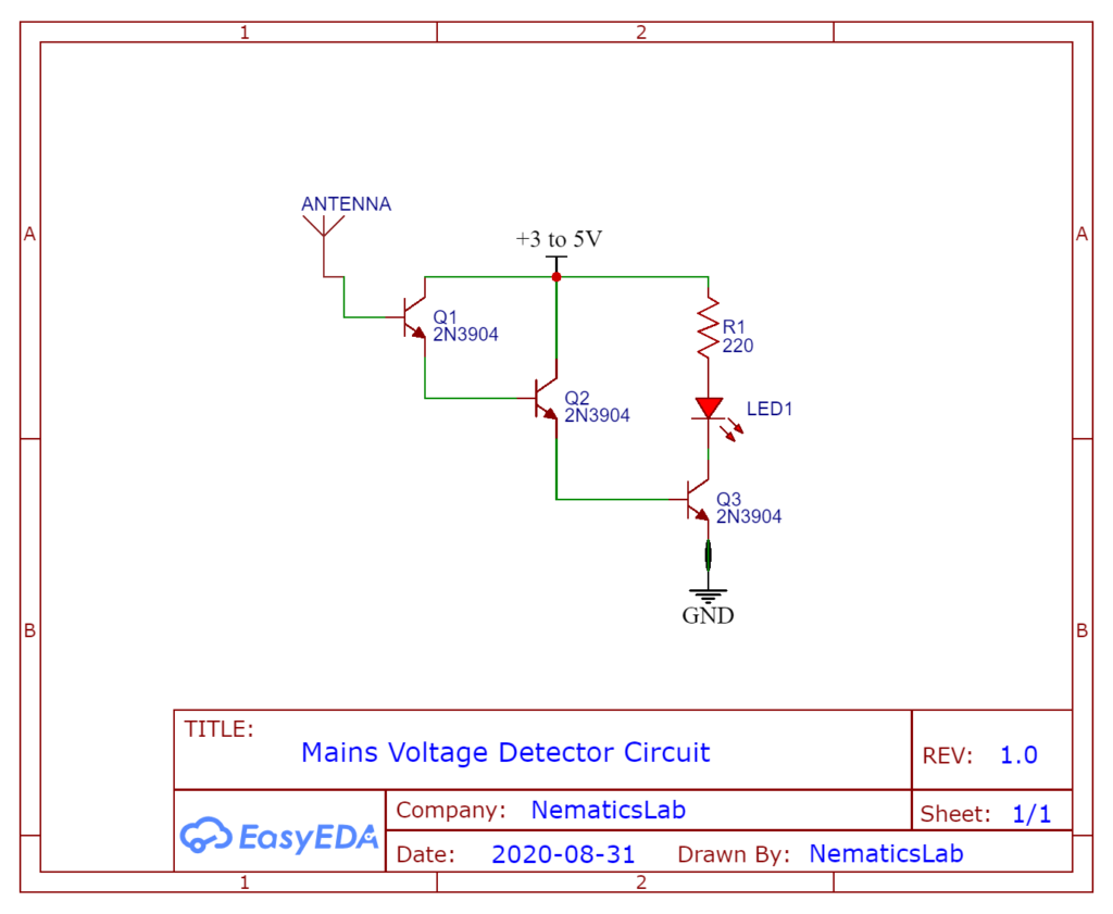
Schematic
Working
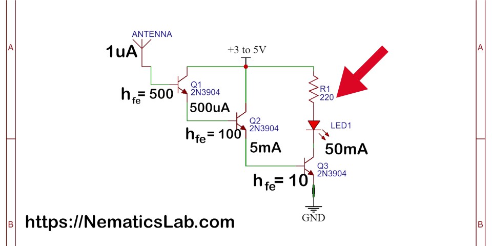
The antenna is connected to the base of First transistor and we all know transistors are used for amplification. So, when the live wire is detected by antenna due to Electromagnetic induction. It induces a Very small current into the antenna let’s say its 1uA. Now this current enters to the base of 1st transistor and gets amplified by an amplification factor of transistor. Known as Beta or hfe generally this hfe value if very large like 500.
So, this 1uA gets by amplified by 500 so the output will be 500uA. And then again since emitter of 1St Transistor is connected to bases of 2nd transistor. This 500uA gets again amplified by the hfe or beta of 2nd transistor let’s say this time hfe is 100
So, this 500uA will get amplified by 100 so output will be 5000uA or 5mA. And lastly you guessed it right this 5mA gets again amplified by 3rd transistor. Let’s say this time Hfe or beta is 10 then this time the Output current will be 50mA. Which is more than enough to dive this LED which only requires 20mA to operate.
Tip: Darlington Pair
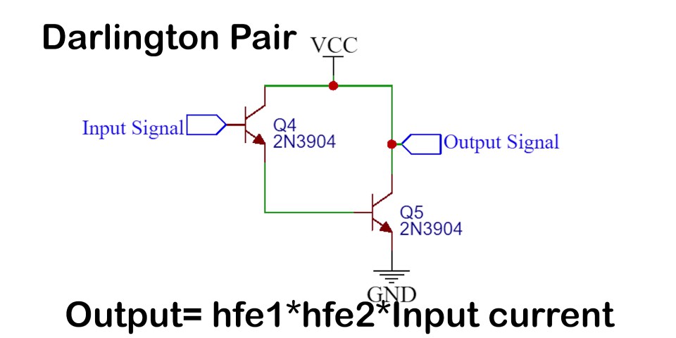
Alright I hope I made sense. And here is a small tip or fact for you guys. If you ever encounter this kind of circuit where Emitter of 1st transistor is connected to base of 2nd transistor. This circuit is known as Darlington pair. You can simply multiply gain of both transistors and output will be same.
Soldering

Finally all we have to do is solder the circuit as per the schematic
Once the circuit is complete, we need to attach an antenna which is basically a capacitor. For that we are going to use a long piece of wire and wound it around the screwdriver to make a helical antenna. And simply solder one of its ends to the base of first transistor. And Now all we have to do is give some power to this circuit. You can give anywhere from 3-5V DC as power I’m using a simple 3.7V Li-ion cell.
Testing
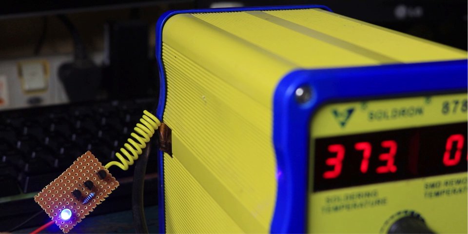
Once that is done now if we move this antenna over any live wire and the LED glows. So that pretty much it for this tutorial.
You might also like this tutorial :-


