Introduction,
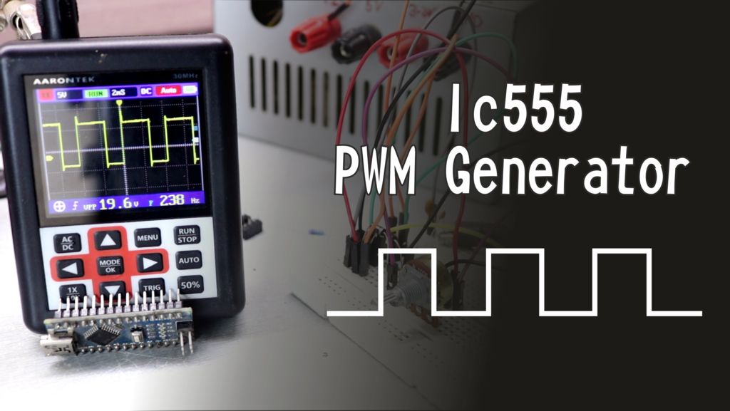
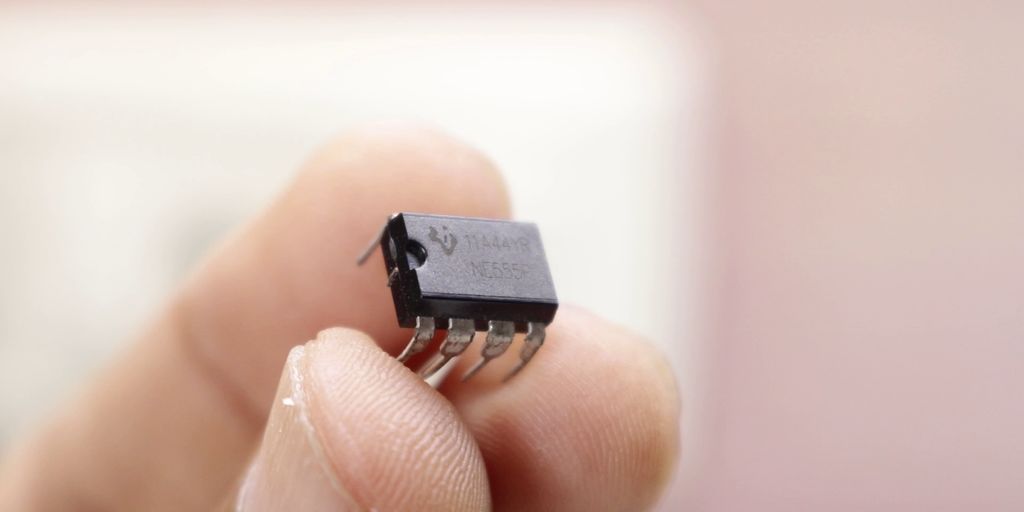
We use Pulse Width Modulation (PWM) in today’s world due to its requirement for controlling many devices in the field of Electronics. We need PWM signal widely for controlling motors, dimming LED lighting and more. Sometimes, we don’t use microcontroller in our applications. If we need to generate PWM without microcontroller then we prefer some general purpose ICs like op-amp, timers, pulse generators etc. Here, we are using a 555 timer IC for generating PWM. Timer IC is a very useful and general purpose IC which can be used in many applications.
What is PWM signal?
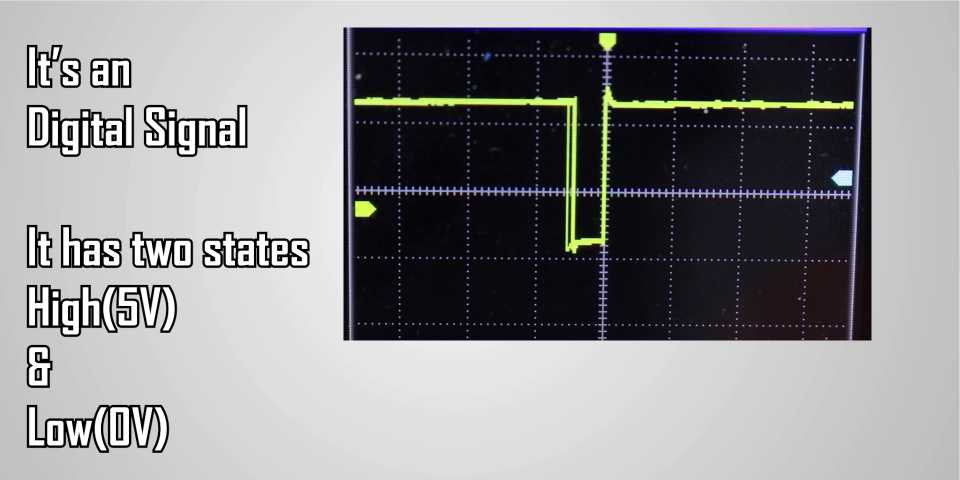

Before we start, we need to understand what PWM actually is. It is an electrical signal (called as pulse) in given period of time interval (known as frequency of the signal). When we see the signal at its HIGH value for certain time, we call it as ON time. When we see the signal at its LOW value for a certain time, we see its OFF time.
The percentage of time in which it remains ON is called as the duty cycle of the signal.
Schematic,
Step 1: Assemble the circuit

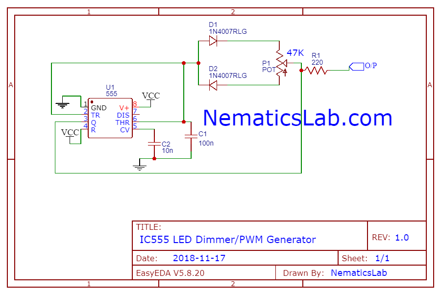
We need to assemble the circuit to see if it is working. According to the schematic, we control the output signal of PWM using capacitor C1 and potentiometer P1. We can calculate the frequency using the following formula:
Frequency= 1.44/(P1*C1)
We can also control the duty cycle by rotating the potentiometer.
Step 2: Test the circuit
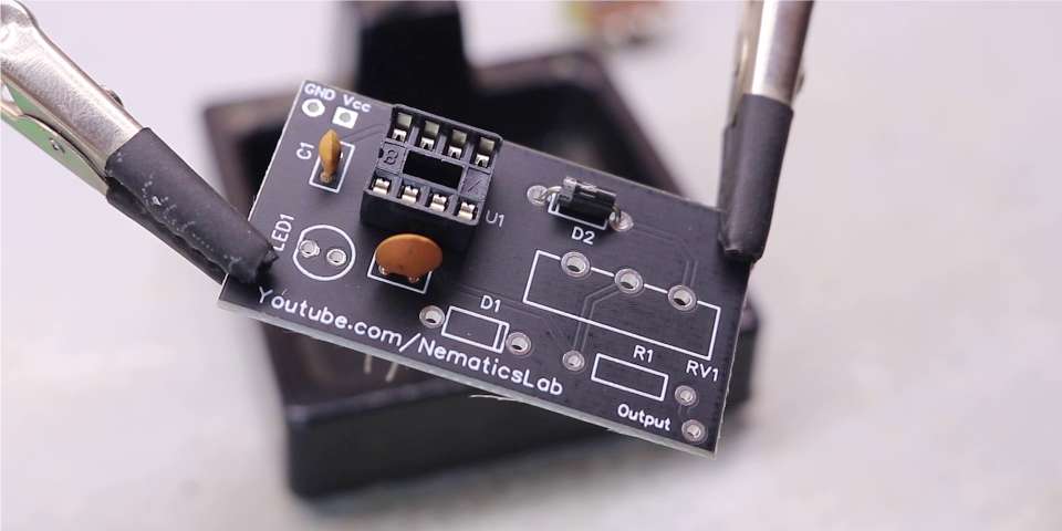
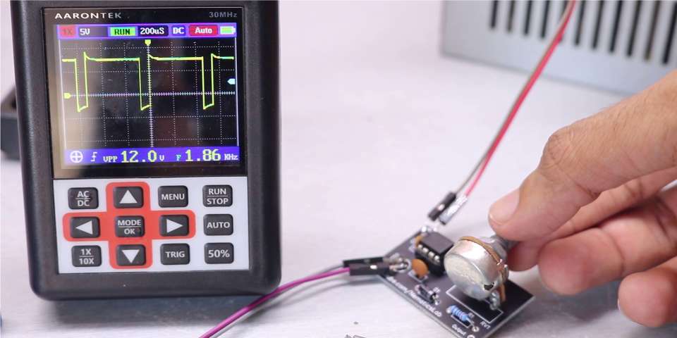
We need to check the PWM signal by attaching the probes of oscilloscope to the circuit assembled on breadboard. After we confirm the circuit to be working successfully, we can create a PCB for the same circuit. After obtaining the PCB, solder all the components in their places.
Step 3: Completion
Once done with soldering, check the output of PWM signal. And the project is successfully complete.


