Introduction,
In this tutorial, we will have a look at ESP01 Wi-Fi module and learn how you can program it using Arduino IDE, which can be really useful if you only wish to control few GPIOs Pins, So lets see how to use it!
Everything we need,
Pin out of ESP01
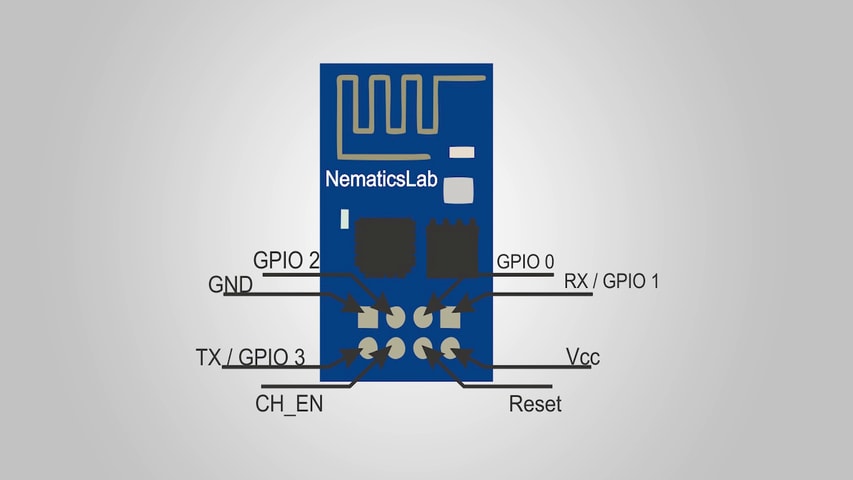
Firstly, let’s start with Pinout, This tiny ESP01 module has a total of 8 pins, and pinout is shown above
If you are not using Rx and Tx lines in your project you can use those as GPIO1 & 3 respectively. While working with this module keep in mind that it works with 3.3V So don’t accidentally connect it to 5V it will destroy it. Since this tiny module costs only $2 whereas an ESP8266 Node MCU board can cost you around $12 it can be a great alternative which is cheaper if you are just using few GPIOs.
Programming using FTDI
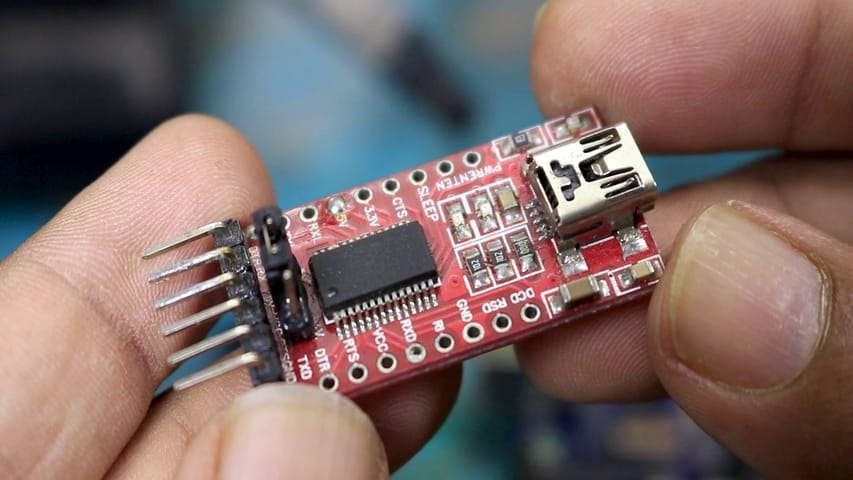
Now let’s see how to program it. For programming you can use and pretty much any Arduino or an FTDI breakout board. I prefer this type of FTDI because it has an option for 3.3V and 5V levels all you have to do is change the jumper position. But if you wish to use an Arduino you can do so, just head over to the next step.
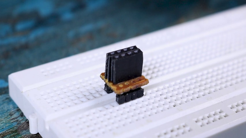
Before we can start programming you will need to make an adapter board like this one. Since the pins on this ESP01 module are not bread board friendly. Once you have your module on breadboard.
Connections for Programming
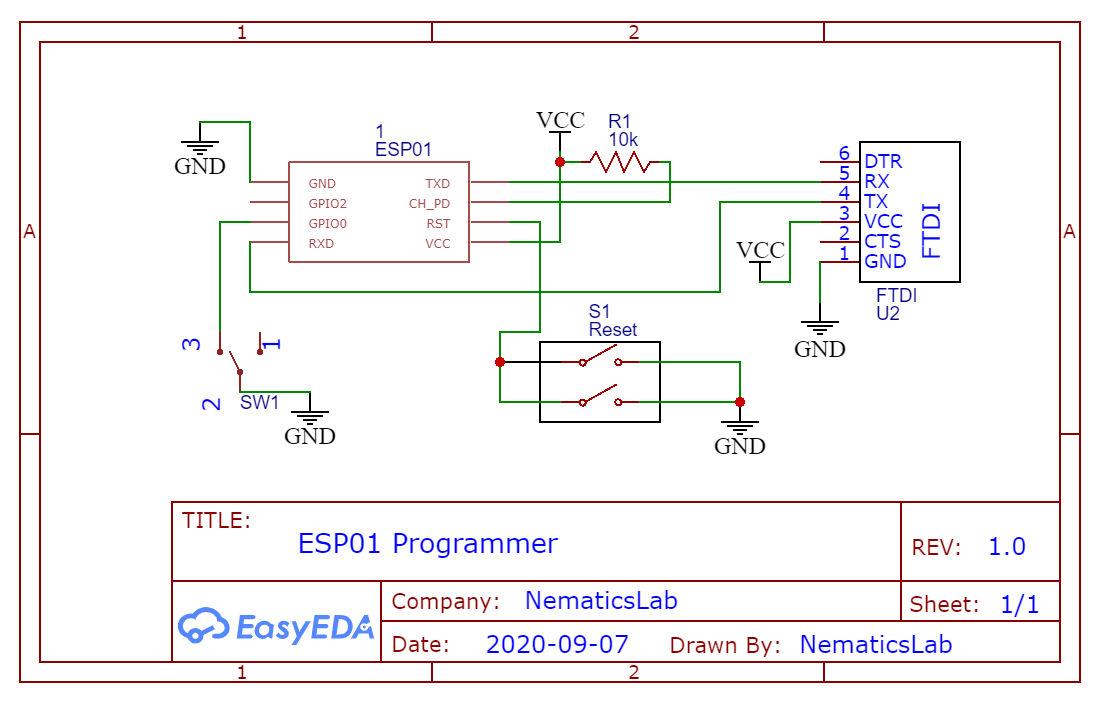
Firstly, connect the Vcc & GND to 3.3V and Ground, secondly connect Tx of ESP01 to Rx of FTDI and Rx of ESP01 to Tx of FTDI.
Now that is done connect Chip_Enable pin to 3.3V and Lastly to put this ESP01 into Programming Mode connect GPIO0 to GND. Additionally you can add a pushbutton between ground and Reset or you can do it manually later.
Uploading code using Arduino IDE
After connecting USB cable to FTDI, Now open the Arduino IDE, select the Port of your FTDI before doing so make sure to install Drivers of FTDI board.
Check out – How to install FTDI Drivers
Now in the Arduino IDE select the board as Generic ESP8266. If you don’t see this board you might want to check out my previous video which shows how to install ESP8266 boards into Arduino IDE.
Also Check out – How to install ESP8266/ESP32 Boards in Arduino IDE
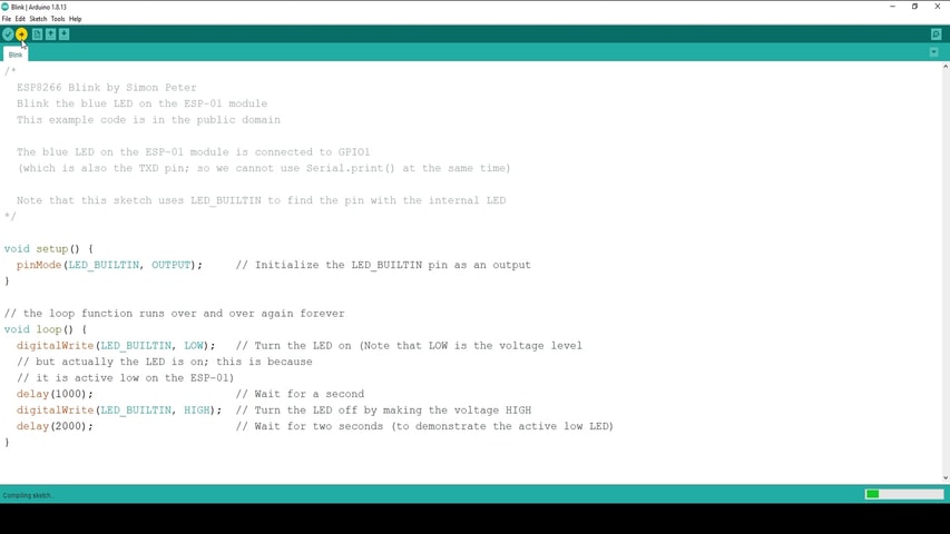
Now open the Blink Example. And all you have to do is upload the code. After a hitting upload it will show connecting and then it will start uploading the code.
Once the uploading is done, remove the GND wire from GPIO 0 and reset the ESP01 using pushbutton.
This will put the ESP01 into mode where it will run the code we just uploaded. Now connect an LED between GPIO2 and GND and if you did Everything correctly LED will start blinking. So that is how you program ESP01 Wifi Module.
Programming using Arduino Uno/Mega/Nano etc.
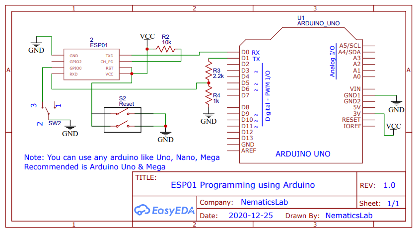
To program ESP01 using Arduino its same process just follow the above schematic. And steps shown in previous steps.
So that’s pretty much it for this tutorial guys I hope you enjoyed this tutorial, Stay tuned for next tutorial and as usual like share and Follow and I will see you guys in the next one!