Introduction
If we have a power supply which has not been in use for some reason, we don’t need to throw it. We can convert it into a bench power supply using electronics. We can use it for many electronics projects. In this project, we will see how we can make our bench power supply using ATX PSU.
Electronics Starter kit Tools:
Soldering Iron – https://www.banggood.in/custlink/DKGKUAqCKa
Solder wire – https://www.banggood.in/custlink/mv3vks2ROf
Helping Hands – https://www.banggood.in/custlink/vmvmMAqd0C
Hot Glue – https://www.banggood.in/custlink/D3GDMAkWDS
Step 1: Understand the internals of power supply
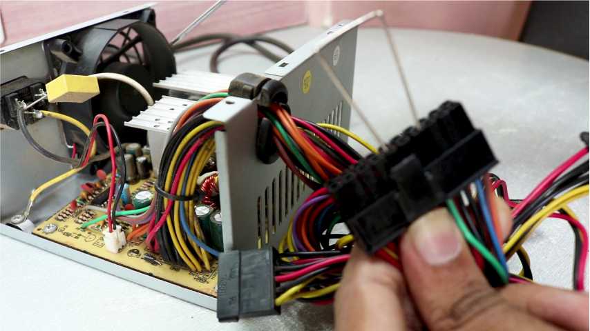
We first need to unscrew the casing of power supply to take a look at its internals. In the internal, we have several capacitors. We should never carelessly handle them. They might have charge in them. Which can be fatal if not handled properly. We also need to check if it is working. So, we can connect the green wire from 24 pin connector to any of the black wires. If the fan starts to spin, then we can be assured that the supply is in working condition.
Step 2: Conversion into lab bench power supply

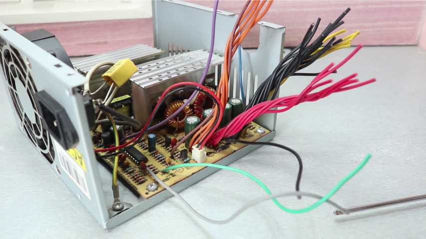
We need to trim the wires because we do not need the connectors. Then we should arrange the wires according to their colours. Red wires are for +5V, Yellow wires are for +12V, Orange wires are for +3.3V, along with the Brown wire which needs to be connected. Blue wire is for -12V. We don’t need the rest of the wires in this project.
Step 3: Assembling the supplies


Leaving 1 red, 1 green and 2 black wires, we should solder all the wires together as per their colour. Solder orange wire with the brown one, otherwise it won’t work. We should solder the green wire with the black, so that power supply will always be ON (Also we can add a switch). To obtain a stable output, we need to add a dummy load. For that we can use 5ohm, 10W resistor. After that, we solder red wire to one side and black wire to the other side, covering it with an electrical tape.
Step 4: Final mechanical-electrical assembly
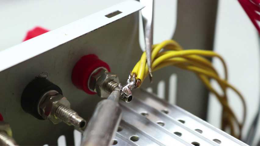
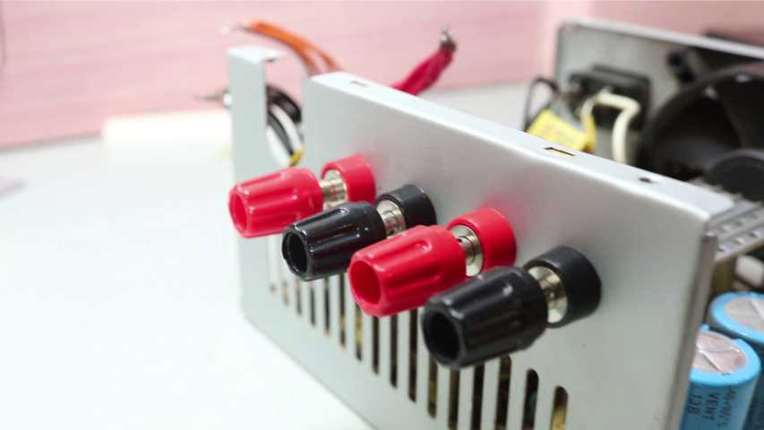

We need to drill four holes in the casing to attach banana connectors in them. Now, we need to solder the wires as per their groups (12V, 5V, 3.3V, and ground). Others can attach differently according to their wish. And we can check the voltage between terminals to see that it is successfully working.